Note: This article was originally published by me on Habr: https://habr.com/ru/articles/793326
The CAN protocol is now widely used not only in the automotive industry but also in enterprises, various DIY projects, and even in Personal Mobility Devices (e.g., VESC controllers). Last November, I created a handy tool for analyzing CAN and sending frames. Now, I want to make the code open-source (MIT License) and talk about the project itself. For the impatient, here's the link to the code: https://github.com/okhsunrog/can_wizard
Let's get started!
Introduction
First, I'll tell you what pushed me to create it. At my last job, and later in my own projects, I often had to deal with CAN bus analysis and the need to send frames for debugging and testing. At first, the problem was solved with an Arduino Uno board and a standard CAN board from Aliexpress, which was connected via SPI and contained an MCP2515 CAN controller and an MCP2551 transceiver. The firmware was created on the fly in 5-10 minutes and was as simple as possible: it outputted received CAN frames to UART and had the ability to send a limited, hardcoded number of frames. I was too lazy to parse data from UART and convert it into a frame. Then, when I got tired of making changes to the code and re-flashing the Arduino for each new board/command, I thought about a better option. At work, I had just made a few shields for the Raspberry Pi containing MCP2551 + SN65HVD230. Then I made the same for myself at home, working with CAN by opening two windows in tmux: candump + cansend. After a few months, I realized that I was keeping the Raspberry Pi on my desk just for CAN testing: I already had a fairly powerful home server on x86_64 and I didn't see any tasks for which I would also need a Raspberry Pi. It was decided to create a small, portable, cheap and cheerful solution that would have the following functionality: receive and send CAN frames, configure the CAN operating frequency, set custom filters for incoming frames, and monitor the number of errors on the CAN bus. Since I was doing all new projects on the esp32-c3 at the time, it was decided to do it on that.
Why esp32-c3?
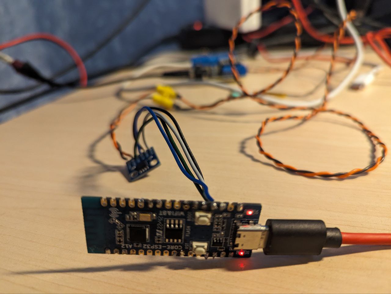
At the moment, among microcontrollers, my favorite is the esp32 family from Espressif. An important feature for us is that almost all esp32 microcontrollers have a CAN controller, so we will only need a transceiver, which will simplify assembly and reduce the final cost. Of course, CAN controllers are also present in some stm32 chips, but at that time I was doing all current projects on esp32 and there was no stm32 dev board at hand. The esp32-c3 was chosen specifically because of its lowest cost, while its peripherals are more than enough for us, because of the usb-serial built into the chip, and the errata section in the datasheet is much more modest than that of the older esp32. By searching "esp32-c3 board" on Ali, you can find boards that cost only 180 rubles. I liked them so much that I bought 20 of them. As a physical layer chip, we will use the good old SN65HVD230. On Ali, there are modules with this chip for 50-90 rubles (the more expensive the module, the cheaper the delivery). The total price of the esp32-c3 dev board + the board with the transceiver + delivery comes out to about 3 dollars.
Okay, but what are we going to write the software in?
This time - in good old C! We will use the official esp-idf framework from Espressif. It is a very powerful thing with good documentation and a bunch of code examples. Under the hood, it has a forked FreeRTOS, but since our chip is single-core, the differences with the original FreeRTOS are insignificant and can be ignored. This time we will not experiment with C++ support in esp-idf and link C and C++ code together, let alone the toy Arduino. We will also not touch on the newfangled Rust for now, the support for which Espressif is now very actively introducing (commits are pouring in very actively, I plan to talk about this in the next article). Basically standard libraries + a simple implementation of a singly linked list, connected as a component. Once at university we wrote similar things in C as homework, but here I got lazy and just took the simplest implementation of a Linked List from gitlab, fixed it a bit and tweaked it for myself. A component for working with CAN is already included in esp-idf, and it is well documented. By the way, Espressif calls it not CAN, but TWAI, because it does not support CAN FD, only classic CAN. I don't see much point in this name, but since they renamed it, it means it's easier for someone 😃
And now let's talk about a very important thing, in fact, the main feature of this project - an interactive console that provides us with the ability to register commands, a REPL environment, line editing during input, multi-line input, auto-completion, hints, command history navigation, GNU-style arguments for commands. These features are provided to us by an esp-idf component called Console. In more detail - linenoise is responsible for line editing, hints, completions, and input history, and argtable is responsible for parsing arguments. The Console component itself is responsible for the REPL environment. Naturally, the libraries there are not the latest version, and are heavily edited for compatibility with esp-idf. However, this component did not allow me to implement exactly what I wanted, which is why I had to create a fork. In the fork, I synchronized the changes in the original linenoise with the version from esp-idf, fixed a few nasty bugs, and also added support for an asynchronous API. What is it and what is it for? I really wanted the display to update not only during user input, but also when a new CAN frame is received. And they should not interfere with each other. To do this, you need to erase the prompt line for a moment, display a message, and then draw the prompt again. In this case, you must not lose the command text entered by the user. I also wanted to add useful information about the current CAN status to the prompt itself. Asynchronous API support appeared in linenoise after a significant refactoring and rewriting of part of the functionality, so I had to spend a significant amount of time to have both the new library functionality and the patches from esp-idf necessary for compatibility with esp-idf in my fork. Unfortunately, at that time I did not figure out how to do something similar to Serial.available() or select(2) in esp-idf (namely, checking for new characters in the uart buffer, without reading). Subsequently, I found the uart_get_buffered_data_len() function, but at that time it was decided to add the SemaphoreHandle_t stdout_taken_sem semaphore. Thus, the process can be blocked, waiting for user input, while another process outputs derived text to the console. The semaphore does not allow linenoise to output data to the console until we finish our output.
More about the code structure
The entry point in esp-idf is the void app_main(void); function. In it, we first initialize uart_tx_ringbuf - an additional buffer used to output our frames and logs to the console. Its purpose will be described in more detail below. Next, we create the can_task process - it is responsible for monitoring the CAN state by periodically checking twai_read_alerts, restoring the CAN bus after an error, as well as for receiving frames, filtering them in accordance with software filters and sending them to the uart_tx_ringbuf Ring Buffer for further output to the console. Also in can.h, the SemaphoreHandle_t can_mutex is declared, which is used to prevent the user from stopping the CAN interface with the candown command while the can_task process is blocked by the twai_receive function - this would lead to a panic and the esp32 would reboot. Instead, to stop the interface, we wait until twai_receive receives a frame, or times out, set in the can_task_timeout variable. I set this value to 200 ms, considering it optimal. If you set the value too large, there will be too long a delay when trying to stop the interface, and if it is too small, the average delay between receiving a frame and outputting it to the console will increase.
Next, we initialize the file system. The command history is stored in a small fat32 partition in our flash memory. Next comes the initialization of the console, where we configure the parameters of the built-in USB-UART interface of our esp32-c3, configure the Console component, load the command history from the file system, and register commands and their handler functions. After that, the console_task_interactive process is launched. This process creates a prompt, launches the linenoise handler, which provides all the interactive input. This process also handles the commands entered by the user. From this process, another one is created: console_task_tx, which is responsible for outputting information to the console. It receives data from the aforementioned uart_tx_ringbuf and outputs it to the console as follows: it hides the prompt using linenoiseHide(), outputs the data from the Ring Buffer + updates the prompt (as I said, it contains the current CAN status and the number of errors), or simply updates the prompt if the 200ms timeout has expired. Then the prompt is displayed again using linenoiseShow(). Here, the aforementioned stdout_taken_sem is used to prevent linenoise from interfering with our output. A second semaphore, console_taken_sem, is also used for synchronization - it is needed so that there are no attempts to output to the console while the entered command is being processed - attempts to hide and show the prompt would otherwise work incorrectly, since the entered command is processed after linenoiseEditStop() and before the next call to linenoiseEditStart().
Adventures with printf
A logical question that may arise is how does the output of information and logs to the console work? esp-idf actively uses the ESP_LOGI, ESP_LOGE, ESP_LOGW, etc. macros for logging, and it is not particularly concerned that outputting something extraneous to the UART might greatly displease linenoise (remember how we carefully tried to synchronize our information output with it using semaphores?). Fortunately, esp-idf is quite flexible and provides us with the esp_log_set_vprintf function. With it, we can set our vprintf_like_t function like this: esp_log_set_vprintf(&vxprintf);. The implementation of the function itself:
// This function will be called by the ESP log library every time ESP_LOG needs to be performed.
//      @important Do NOT use the ESP_LOG* macro's in this function ELSE recursive loop and stack overflow! So use printf() instead for debug messages.
int vxprintf(const char *fmt, va_list args) {
    char msg_to_send[300];
    const size_t str_len = vsnprintf(msg_to_send, 299, fmt, args);
    xRingbufferSend(uart_tx_ringbuf, msg_to_send, str_len + 1, pdMS_TO_TICKS(200));
    return str_len;
}
Excellent! Now the ESP_LOGx macros do not print data to the console, but send it to our Ring Buffer, from where console_task_tx prints it. But what about printf in our code? It can also break everything. No problem, instead of printf we will use our own xprintf function, which uses the one we just wrote:
int xprintf(const char *fmt, ...) {
    va_list(args);
    va_start(args, fmt);
    return vxprintf(fmt, args);
}
Also, for greater convenience, a function was implemented that can print text using printf/xprintf (regular printf - for output from the command handler when linenoise is inactive) in a color we specify + optionally print a timestamp before the message:
int print_w_clr_time(char *msg, char *color, bool use_printf) {
    print_func pr_func;
    if (use_printf) pr_func = printf;
    else pr_func = xprintf;
    char timestamp[20];
    timestamp[0] = '\0';
    if (timestamp_enabled) {
        snprintf(timestamp, 19, "[%s] ", esp_log_system_timestamp());
    }
    if (color != NULL) {
        return(pr_func("\033[0;%sm%s%s\033[0m\n", color, timestamp, msg));
    } else {
        return(pr_func("%s%s\n", timestamp, msg));
    }
}
The interactive console is great. What commands are implemented?
helpcommand - detailed help on all commands.- cmd_system.c
free- displays the amount of free memory in the heap.heap- displays the minimum amount of free memory in the heap since the esp32 started.version- displays the esp-idf version used to compile the project, information about the chip, and the flash memory size.restart- reboots the esp32.tasks- displays a description of the running FreeRTOS processes, in our case it is something like this:error active [TEC: 0][REC: 0] > tasks Task Name Status Prio HWM Task# console tsk int X 2 5964 5 IDLE R 0 1244 3 can task B 5 2916 4 console tsk tx B 2 3248 7 esp_timer S 22 3860 1log_level- allows you to set the logging levelnone/error/warn/info/debug/verbosefor each LOG_TAG separately, or for all together.
- cmd_utils.c
timestamp- enable or disable the output of timestamps for received and sent frames.
- cmd_can.c
cansend- it's obvious, sends a CAN frame. The syntax is made a bit similar to the syntax of cansend from the Linux can-utils. That is, the frame is sent like this:cansend FF00#0102FE. The ID type (extended or standard) is determined by the length of the ID. Less than 4 characters is a standard ID, otherwise it is extended.canup- Installs the CAN driver and starts the interface. It takes the interface speed as input, and, optionally, the mode and two flags. The speed can be any of1000/5000/10000/12500/16000/20000/25000/50000/100000/125000/250000/500000/800000/1000000. The default mode isnormal, but there are alsolisten_onlyandno_ackmodes. The-rflag enables automatic recovery of the interface after going into bus-off due to a large number of errors. The-fflag enables previously set filters, otherwise all frames are received and displayed.candown- stops the interface and removes the driver. Useful if you want to run CAN with different parameters (see the previous command), or change the filters.canstats- displays CAN statistics: status, TX Err Counter, RX Err Counter, Failed transmit, Arbitration lost times, Bus-off count.
Tip: the status and RX/TX Err Counter are also displayed in the prompt.canstart- starts CAN when the driver is already installed. Useful for manual recovery from bus-off, it is started aftercanrecover.canrecover- manual recovery from the bus-off state.canfilter- sets CAN frame filtering, accepts mask, code,dual filer modeflag in full accordance with the esp-idf documentation, uses the standard framework filtering. If you want to use this type of filtering, read the page about TWAI in the esp-idf docs.
Filters must be set before executingcanup. Do not forget to specify the-fflag forcanupso that it picks up the filters.cansmartfilter- a sophisticated filter, my pride! It combines software and hardware filtering, a very flexible thing. I have long planned to implement something like this for the esp32, and now, I have finally done it.
Filters must be set before executingcanup. Do not forget to specify the-fflag forcanupso that it picks up the filters.
It was a separate pleasure to write the argument parsing for all this miracle 😃
cansmartfilter - what's that beast?

The thing is, the CAN controller in the esp32 has rather limited capabilities for filtering frames by ID - only 1-2 patterns, and if you need two patterns with an extended ID, only part of the ID will be filtered. We can select common bits and filter by them, but sooner or later this will not be enough - we will have to use software filtering. As an example of a CAN controller with a large number of hardware filters - MCP2515.
But let's not be sad, let's solve an interesting problem! So, our cansmartfilter command can take from 1 to CONFIG_CAN_MAX_SMARTFILTERS_NUM filters. By default, I set this value to 10, but if desired, it can be increased, the main thing is that there are enough microcontroller resources, you can set 20 filters, or more. Filters are entered in the code#mask format. I have not yet implemented filtering of frames with a standard ID in cansmartfilter, because this is not used in my devices, there is only filtering of frames with an extended ID. To filter frames with a standard ID, use canfilter. In the general case, the command looks like this: cansmartfilter 11223344#FFEECCBB 33123A#23BBE0 90#AB - here we have set 3 smart filters. mask and code are uint32_t numbers in hex format. Ones in the mask mean the bits that are taken into account by the filter, zeros are the bits that are ignored. For example, a filter like 0000FF00#0000FFFF will only accept frames that start with FF00, there is no filtering on the other bits. That is, 0029FF00 and 00ABFF00 will pass, but 00ABFF05 will not. As you can see, everything is very simple, and you can set quite a lot of filters.
Now about how it is arranged under the hood. Yes, this is where the Linked List came in handy for me - to store a list of filters. A list of elements of this type:
typedef struct {
  uint32_t filt;
  uint32_t mask;
} smart_filt_element_t;
In the process of parsing the command arguments, with the help of cunning bitwise logic, it is determined whether it is possible to cover all filters with a hardware filter. This is possible only in 2 cases: either we have only 1 filter, or the set of frames passed by one filter is a subset of the frames passed by another filter. As a special case - if the filters match. In the cases listed above, software filtering is not enabled and the cansmartfilter command can be used as an alternative to canfilter, but with a more pleasant syntax.
Next, the CAN interface is brought up with the canup -f command and filtering begins.
The bits common to all filters are filtered using a hardware filter, and those frames that pass further are filtered in can_task when a new frame is received. Everything is elementary here:
// somewhere in can task
  const BaseType_t sem_res = xSemaphoreTake(can_mutex, 0);
  if (sem_res == pdTRUE) {
      while ((ret = twai_receive(&rx_msg, can_task_timeout)) == ESP_OK) {
          char data_bytes_str[70];
          if (adv_filters.sw_filtering) {
              if (!matches_filters(&rx_msg)) continue;
          }
          can_msg_to_str(&rx_msg, "recv ", data_bytes_str);
          print_w_clr_time(data_bytes_str, LOG_COLOR_BLUE, false);
      }
      xSemaphoreGive(can_mutex);
      vTaskDelay(1);
  }
  if (sem_res != pdTRUE || ret == ESP_ERR_INVALID_STATE || ret == ESP_ERR_NOT_SUPPORTED) {
      vTaskDelay(can_task_timeout);
  }


  bool matches_filters(const twai_message_t *msg) {
      const List *tmp_cursor = adv_filters.filters;
      while (tmp_cursor != NULL) {
          const smart_filt_element_t* curr_filter = tmp_cursor->data;
          if ((msg->identifier & curr_filter->mask) == curr_filter->filt) {
              return true;
          }
          tmp_cursor = tmp_cursor->next;
      }
      return false;
Let's build it!
You can solder and flash it in just half an hour. It will take another half an hour to figure out the commands. After that, you will have a very convenient tool for debugging CAN, cheap and portable.
Startup instructions:
Install the esp-idf toolchain as specified in the official documentation
Clone the repository along with the submodule:
git clone --recursive https://github.com/okhsunrog/can_wizard.gitGo to the
can_wizarddirectoryidf.py set-target esp32-c3idf.py menuconfigIn the menu, find
Can_wizard Configuration --->and edit the parameters to your liking. For example, you will probably want to changeCAN RX GPIO numberandCAN TX GPIO number, and you may also want to changeMax number of smartfilters. It is better not to touch the other parameters unless you are sure what they do. Save with the 'S' key and exit by pressing theEsckey several times.Solder the transceiver board to the esp32-c3 board, you only need to connect 4 pins: 3.3v power, GND, and also CTX and CRX according to the pins for CAN TX and CAN RX that you set in the previous step. Attention: on my board with a transceiver, the pins are signed differently on the front and back of the board. If you have the same problem, the correct markings are on the side of the chip. By the way, the board already has a 120 Ohm terminating resistor. If you don't need it, just desolder it, or even better, move it, leaving one contact soldered. This way you can easily put it back in place if necessary.
Connect usb to esp32-c3 and execute in the terminal
idf.py flash monitorYour terminal must support ANSI escape sequences. GNU screen, minicom, and esp-idf-monitor are known to work.
if you see unpleasant prompt flickering in esp-idf-monitor, try another serial console. For example,
minicom --color=on -b 115200 -D /dev/ttyACM0
Demonstration
https://www.youtube.com/watch?v=ajKFa0b113o
This is my first article, please do not judge too harshly. I would be very grateful for any adequate criticism and advice! In turn, I am ready to answer any questions about the project 😃